Getting Started with Animated Christmas Lights
Use simple, affordable electronics to build an animated lighting display.
The Overview
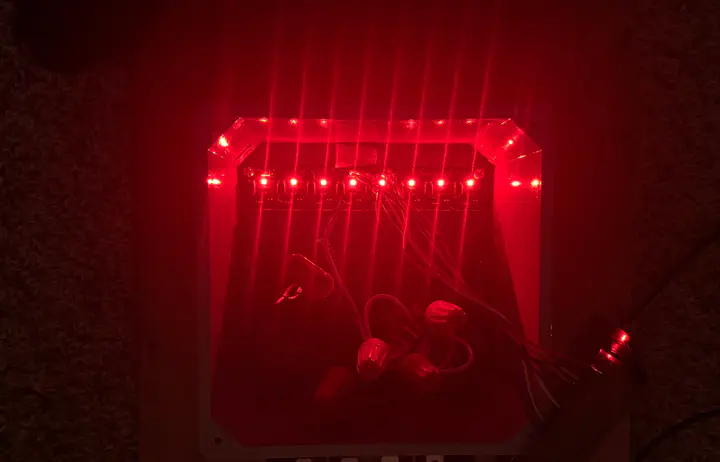
Animated lights that are synced to music have always been fascinating to me, so I took the challenge to create my own display. This article, while it won’t dive into the deep details at every step, will provide an overview of all the steps required to build an animated Christmas-light display at home. There are other resources that will dive deeper if you need in-depth assistance.
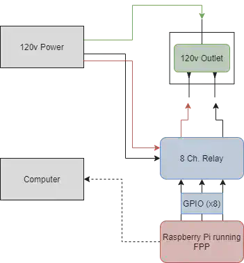
Let’s start with the control software. The brains of the operation is a Raspberry Pi B running custom firmware called FPP. This firmware is based on a web server that can be accessed over the local network. The Raspberry Pi communicates with a piece of hardware called a relay. The relay basically allows the Pi to switch high-voltage power on an off rapidly. The last step of the process is the 120v (mains) power. The power, which is controlled by the relay, is distributed to 8 outlets that are each controlled by a channel on the relay board.
The Details
Before diving into the details, let’s look at a overview of the parts required. In reality, this project can be done for about ~$100USD all told, which is quite a bargain.
Parts List (Required):
- 1 x Raspberry Pi 3 B + Supporting hardware. If you don’t want to figure out all the pieces of the Raspberry Pi, you’ll want to get a kit from CanaKit.
- 1 x SainSmart 8ch. Relay
- ~20ft of 120v solid copper wire
- 8 x 120v outlets
- 10 x 8in Dupont Wire
- 1 x Power Supply Wire
Parts List (Recommended):
- 1 x 5in Weathertight box
- Conduit
- Conduit Fittings
- Plastic Cement
Step 1: Install FPP
The first step is to set up your raspberry pi. If you bought the CanaKit, use the included microSD adapter to mount the SD card to the computer. Flash the latest version of FPP and configure your basic settings. See https://falconchristmas.github.io/FPP_Manual.pdf for more details on setup.
Step 2: Wire up the relay board
In order to test the relay, you need to wire up everything. The relay is connected to the Pi with the DuPont cables. There are a total of 10 pins on the relay. The pins on each end, labeled `GND` and `VCC`, are the power supply for the board. The 8 pins in the middle each control a relay channel. Your board may have a different pinout order, so make sure to do your own research.
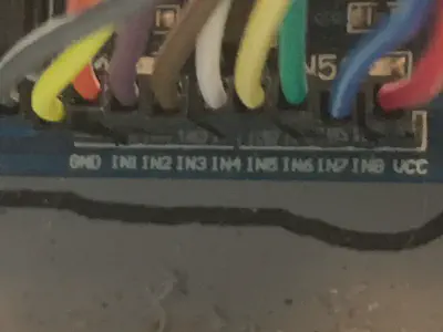
Take and wire up the ground (GND) and voltage (VCC) pins. Use the image below to locate the correct pin.
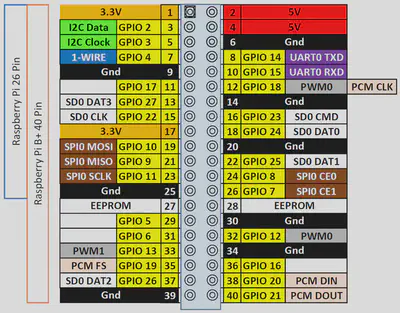
Once you have wired up the power, wire the first pin to an open GPIO pin on the Pi. Using the chart above, make a note of the pin number. Repeat for each remaining pin.
More on the software will be coming soon!